3D-Printed
Wrist Exoskeleton
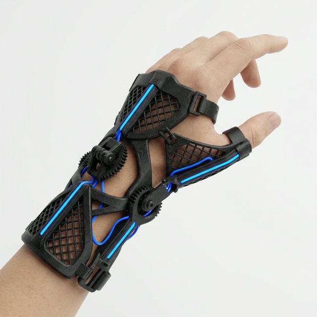
A lightweight, fully 3D-printable wrist-assist exoskeleton designed to support flexion and extension movements. Driven by a single servo, guided by flex sensors, and controlled by an Arduino Nano — this is a complete build guide covering every component, print setting, and assembly step.
What Is This Build?
The EXO-W1 (Wrist Exoskeleton, Version 1) is a research-grade wearable device that assists the natural wrist flexion–extension range of motion. It was designed as a mechatronics capstone project and as a platform to learn about biomechanical mechanism design, embedded sensing, and closed-loop actuator control — all in a single, wearable package.
The entire structural frame is 3D-printable in PLA or PETG. It uses a single MG996R metal-gear servo as the prime actuator, a flex sensor glued to a glove liner as the intent-detection input, and an Arduino Nano as the brain. Total BOM cost comes in under €60.
This guide walks through every step: the parts you need, how to print them, how to assemble the mechanical structure, and how to wire and flash the electronics.
STL Files & Print Configuration
All structural parts should be printed with the following settings for adequate strength and dimensional accuracy.
Recommended Settings
| Material | PETG (preferred) or PLA+ |
| Layer Height | 0.2 mm |
| Infill | 35% Gyroid |
| Perimeters | 4 walls |
| Support | Tree supports, PLA interface |
| Bed Adhesion | Brim — 5 mm |
| Nozzle Temp | 240°C (PETG) / 215°C (PLA) |
| Bed Temp | 80°C (PETG) / 60°C (PLA) |
Parts to Print
- ×1EXO-W1_Forearm_Shell_LNo supports
- ×1EXO-W1_Forearm_Shell_RNo supports
- ×1EXO-W1_Servo_MountTree supports
- ×1EXO-W1_Wrist_Pivot_ANo supports
- ×1EXO-W1_Wrist_Pivot_BNo supports
- ×1EXO-W1_Hand_Dorsum_PlateTree supports
- ×2EXO-W1_Finger_Guide_RailNo supports
- ×1EXO-W1_Electronics_Bay_CoverBrim
- ×4EXO-W1_Strap_BuckleFlat-print
Important Print Notes
All bearing seats and servo-horn holes are modelled at nominal size. If your printer runs tight, ream M3 holes with a 3 mm drill bit after printing. Do not heat-force the servo horn or you will crack the pivot.
PETG is strongly preferred for the pivot and servo mount parts — it handles repeated mechanical stress and moderate heat far better than standard PLA, which can creep over time near the servo body.
Print the Forearm Shells standing vertically (along the long axis) so layer lines run parallel to the strap load direction. This gives the best tensile strength across the shell walls.
Sand all bearing seats lightly with 400-grit. Apply a thin coat of super glue to nut pockets before pressing nuts in — this prevents them from spinning when you tighten bolts from the other side.
Components & Products
Everything you need to build a complete EXO-W1. Quantities are per one unit.
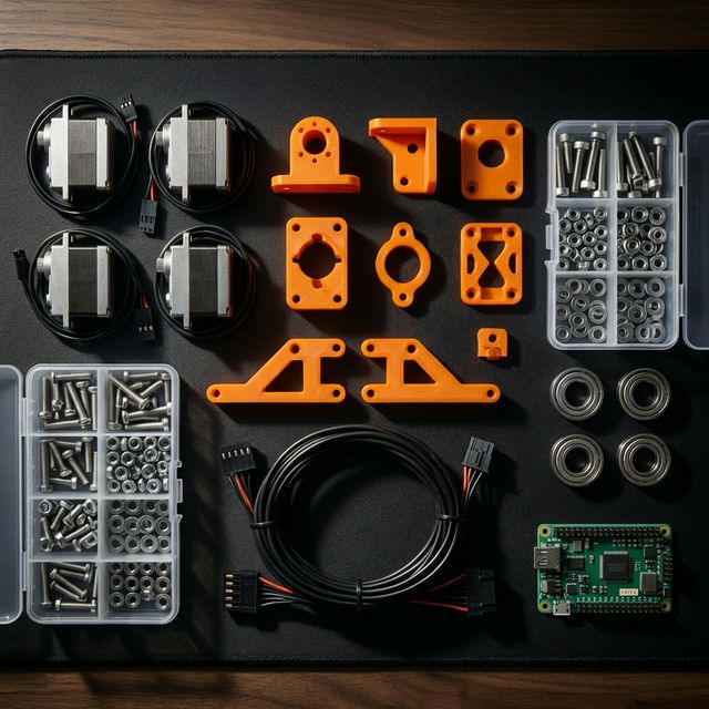
All components before assembly — sorted and ready.
Hardware & Fasteners
| Qty | Item | Spec | Notes |
|---|---|---|---|
| ×18 | Socket-head cap screw | M3 × 8 mm | Shell side panels |
| ×12 | Socket-head cap screw | M3 × 12 mm | Servo mount & pivots |
| ×6 | Socket-head cap screw | M3 × 16 mm | Wrist pivot axle |
| ×4 | Socket-head cap screw | M3 × 20 mm | Electronics bay |
| ×24 | M3 hex nut | Standard | Press into nut pockets |
| ×8 | M3 nylon lock nut | Nyloc | Moving pivot joints |
| ×4 | Radial bearing | MR83 (3×8×3 mm) | Wrist pivot |
| ×2 | Radial bearing | 605ZZ (5×14×5 mm) | Forearm shell pivots |
Electronics
The compact size makes it ideal for fitting inside the electronics bay. Any Nano-compatible clone works fine. Solder header pins before installing.
Metal gears are mandatory here — plastic gears will strip under repeated load cycles. The MG996R's torque is more than sufficient for wrist-assist at this scale.
Taped to the back of a thin glove liner over the wrist joint. Wired as a voltage divider with a 47 kΩ resistor into the Arduino ADC.
Powers the Arduino and servo directly. The Nano's 5V rail can pass through to the servo — 2A peak is sufficient for MG996R at this load. Mount to forearm strap with velcro.
Used for prototype wiring before soldering. Final build should use a custom perfboard layout to reduce bulk inside the electronics bay cover.
Three straps secure the forearm shell to the arm. Thread through the printed buckles and trim to fit. Medical-grade velcro is more comfortable for extended wear.
Tools Needed
Exploded Assembly View
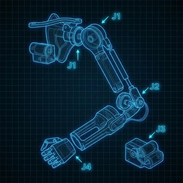
Two-piece clamshell that wraps the forearm. Houses the servo and electronics bay. Closed with M3 × 8 screws.
Two pivot halves joined by an M3 × 16 axle bolt with MR83 bearings on each side. This is the main rotation joint — the servo horn attaches here.
Sits over the back of the hand, attached to the wrist pivot. The two finger guide rails press-fit into slots on this plate and provide gentle support without restricting finger motion.
Bolted to the inside of the right forearm shell with M3 × 12 screws. The MG996R sits flush and is secured with the servo's own M3 mounting tabs.
Recessed cavity in the left forearm shell. The Arduino Nano and voltage divider circuit sit on a half-size breadboard held with double-sided foam tape. Covered by the bay-cover print.
Printed flat in PLA. Three straps thread through them and fold back on themselves with velcro. Buckles are glued to the underside of the forearm shell with CA glue.
Step-by-Step Assembly
Follow each step in order. Do not skip ahead — some steps install parts that become inaccessible later.
Assemble the Wrist Joint
- Press one MR83 bearing into the bearing seat on Pivot_A. The fit should be snug — use a flat surface and press gently with your thumb, or tap carefully with a mallet and a 3 mm dowel.
- Press the second MR83 bearing into Pivot_B in the same manner.
- Align Pivot_A and Pivot_B — the axle hole centres must be co-linear. If they're not twisting freely, check that both bearing seats are fully seated (bearings should sit flush, not proud).
- Insert an M3 × 16 bolt through the axle hole from the A side. Thread on a nyloc nut on the B side. Tighten until there is no play but the joint rotates freely. This is the main wrist joint.
- Repeat for the second axle position (the finger-guide rail attachment point).
Important: Do NOT over-tighten the nyloc nuts. The joint must rotate freely under servo power. If it feels stiff, back the nut off a quarter-turn at a time.
Mount the Servo to its Block
- Press M3 hex nuts into the four nut pockets on the Servo_Mount block. If they feel loose, add a drop of CA glue and let it cure for 2 minutes before continuing.
- Slide the MG996R into the mount cavity. The servo output shaft should protrude through the shaft slot and face upward (toward the wrist pivot).
- Secure the servo with 4× M3 × 12 bolts through the servo's mounting tabs into the nut pockets. Tighten evenly in a cross pattern — do not over-tighten or you'll crack the servo casing tabs.
- Attach the servo horn from the MG996R kit to the output shaft. Use the shortest circular horn (disc horn). The centre-lock screw holds it to the shaft; tighten firmly.
Tip: Before mounting the servo horn, connect the servo to your Arduino and centre it by sending a 90° signal. This ensures the horn is attached at the mechanical midpoint, giving equal range in both directions.
Install Servo Mount into Shell (Right)
- Orient the right forearm shell with the interior cavity facing up. Locate the four mounting pillar holes for the servo mount block — they are on the inner lower wall, with a slot cut for the servo cable to exit.
- Feed the servo cable through the cable exit slot first, then lower the servo mount block into position. The servo output shaft should align with the wrist pivot slot opening at the top of the shell.
- Fasten with 4× M3 × 12 mm screws into the shell's pillars. Tighten until the mount does not rock — if it does, add a thin shim of electrical tape to the contact surfaces before tightening.
- Pull several centimetres of slack cable into the electronics bay cavity side so there is enough length for later connections.
Connect the Wrist Pivot to the Servo Horn
- Press the two 605ZZ bearings into the forearm shell's wrist pivot bearing seats — one on each side wall of the shell opening at the top.
- Slot the wrist pivot assembly between the two bearing seats. The pivot axle should pass through both bearings. It will require light pressure — push from both sides simultaneously to keep it aligned.
- Locate the servo horn connection point on Pivot_A — it has a slot and a single M3 hole. Align this with the hole in the servo disc horn.
- Use an M3 × 16 mm bolt to pin the servo horn to the pivot arm. Add an M3 hex nut on the inside and tighten. There should be no gap — if there is, the pivot will backlash. Use a washer if needed.
Critical: Before closing the shell, manually rotate the servo through its full range and confirm the wrist pivot rotates smoothly from 0° to 70° without binding. If it catches, the servo horn and pivot are misaligned — re-check the horn bolt.
Wire the Electronics
- Place the Arduino Nano on the half-size breadboard. The Nano's USB port should face the bay opening so you can reflash without disassembly.
- Build the flex sensor voltage divider: connect one end of the flex sensor to 5V, the
other end to a node shared with a 47 kΩ resistor to GND. The shared node connects to
Arduino
A0. This gives ~2.5V at neutral and ~4.0V fully flexed. - Connect the MG996R servo cable: Brown → GND, Red → 5V (Nano VIN), Orange → Arduino D9 (PWM).
- Apply heat-shrink to all bare solder joints. Route cables inside the shell so no wire crosses the wrist pivot path.
- Seat the breadboard in the electronics bay cavity and secure with double-sided foam tape. The bay board should sit below the shell rim so the cover fits flush.
// EXO-W1 Wrist Exoskeleton Controller
#include <Servo.h>

Servo wrist;
const int FLEX_PIN  = A0;
const int SERVO_PIN = 9;
const int DEADBAND  = 20;  // ADC counts

void setup() {
  wrist.attach(SERVO_PIN);
  wrist.write(90);  // neutral on boot
  Serial.begin(9600);
}

void loop() {
  int raw  = analogRead(FLEX_PIN);
  int angle = map(raw, 400, 800, 90, 160);
  angle = constrain(angle, 90, 160);

  wrist.write(angle);
  Serial.println(angle);
  delay(20);
}Attach the Hand Dorsum Plate & Finger Rails
- Align the Hand Dorsum Plate with its two mounting tabs over the Pivot_B holes. The plate should lay flat over the dorsum (back of hand) when the wrist is at 0° (neutral).
- Fasten with 2× M3 × 12 mm bolts and hex nuts — hand tighten only so the plate can still flex slightly to conform to wrist shape. You will lock these down fully after fitting to the user.
- Press-fit the two Finger Guide Rails into the slots on the Hand Dorsum Plate. They should snap in firmly. If loose, add a drop of CA glue along the press-fit edge. Let it cure before continuing.
Tip: The finger rails are universal-length and can be trimmed with a hobby knife if they extend past the user's finger knuckles. Trim in 5 mm increments and check fit before cutting more.
Close the Shell and Install Straps
- Align the left forearm shell with the right, checking that the wrist cable and electronics are fully inside the cavity. Press the two halves together — there should be no gap along the entire perimeter.
- Insert and tighten all 18× M3 × 8 mm clamshell screws. Work in a star pattern to close the gap evenly without warping the print.
- Snap the electronics bay cover onto the bay opening and secure with 4× M3 × 20 mm screws.
- Glue the four strap buckles to the underside of the forearm shell with CA glue — two near the distal end and two near the proximal end. Let cure for 5 minutes.
- Thread each velcro strap through its pair of buckles. The straps should be tight enough that the device does not slide when the wrist moves but comfortable enough to wear for 30+ minutes.
Flash Firmware & Calibrate
- Connect the Arduino Nano via USB and upload
exo_w1_control.inousing the Arduino IDE (Board: Arduino Nano, Processor: ATmega328P). - Open the Serial Monitor (9600 baud). With the flex sensor straight, note the raw ADC value — this is your flat baseline. Record the value when bending your wrist fully — this is the max reading.
- Edit the
map(raw, 400, 800, 90, 160)line to reflect your actual flat and bent readings. Re-upload. - Power via USB power bank. The device should now respond proportionally to wrist flex intent detected through the glove sensor.
Congratulations! Your EXO-W1 is complete. If the servo twitches at
neutral, widen the deadband constant in firmware. If response feels lagged, reduce the
delay(20) to delay(10).
// Reflection
What I Learned
Biomechanics Matters
Designing around a human joint is completely different from designing a robot joint. Skin compresses, wrist anatomy varies person-to-person, and the axis of rotation shifts as you flex. Version 1 had a fixed pivot axis that caused the device to slip up the forearm — a problem that required studying actual wrist biomechanics to solve properly.
Iterative Fit Testing
I printed 11 iterations of the forearm shell before getting a comfortable fit. Key learnings: measure the wrist circumference at three points, add at least 4 mm of padding clearance in the CAD, and always test-fit the print dry before adding electronics — you'll need to disassemble it many times.
Intent Detection is Hard
A single flex sensor is a crude input — it can't distinguish between voluntary movement and passive loading. Future versions will use EMG (muscle electrical signals) for true intent detection. This project made me appreciate how much signal processing goes into commercial exoskeleton products.
// Open Source
Get the Files
All STL files, the Arduino firmware, and the SolidWorks source files are available on GitHub under the MIT licence.